Views: 8 Author: Site Editor Publish Time: 2026-10-14 Origin: Site


Choosing an air service unit is not simply a matter of matching a pipe thread. The correct FRL unit must deliver sufficient compressed air at the required working pressure while meeting the application's filtration and lubrication needs.
This practical FRL unit selection guide explains how to compare FR and FRL assemblies, estimate peak airflow, evaluate pressure drop, and prepare an effective specification for industrial automation or OEM equipment.
Key takeaway: Select the FRL configuration based on downstream lubrication requirements, then check peak flow and pressure performance under actual operating conditions. Port size is a connection specification—not proof of airflow capacity.
FRL stands for Filter, Regulator and Lubricator. The filter helps remove particles and separated liquid contaminants, the regulator controls downstream pressure, and the lubricator introduces oil mist where equipment requires it.
The terms air service unit, air preparation unit, and pneumatic maintenance unit are often used for this equipment family. However, an air preparation assembly does not always include a lubricator: many systems use an FR (filter + regulator) configuration instead.
For an introduction to the individual components, see VPC's complete guide to air service units.

The first decision is whether your downstream equipment actually needs oil mist. Adding a lubricator by default is not always beneficial. Many modern cylinders and solenoid valves are designed to operate without external lubrication; check the documentation for each component.
| Selection factor | FR unit (Filter + Regulator) | FRL unit (Filter + Regulator + Lubricator) |
|---|---|---|
| Primary function | Filtration and pressure regulation | Filtration, pressure regulation and oil-mist supply |
| Suitable downstream equipment | Components specified for non-lubricated air | Components explicitly requiring lubricated air |
| Typical consideration | Reduces risk of introducing lubrication oil into the process | Supports lubrication-dependent pneumatic tools or devices |
| Maintenance | Filter service and regulator checks | Filter service, regulator checks and oil-level/oil-type management |
Selection rule: If every downstream device is approved for non-lubricated compressed air, consider an FR unit. Choose an FRL unit when the equipment manufacturer's specifications require an air-line lubricator.
Lubrication requirements should be checked for the entire connected branch. Once lubricated service is adopted for equipment that depends on it, abruptly removing oil supply may create operating problems.
A reliable selection starts with the operating conditions—not the product catalog cover.
Supply pressure: minimum and maximum pressure available at the unit inlet.
Required outlet pressure: pressure needed by the most demanding downstream component while operating.
Peak airflow: maximum simultaneous consumption of connected actuators and tools, with consistent flow units and reference conditions.
Air quality: particle, water and oil limits specified for downstream components.
Lubrication and drainage: whether oil mist is required and whether automatic condensate discharge is desirable.
Installation details: G, Rc or NPT thread; mounting orientation; environment; maintenance clearance; and allowable size.
Engineering note: Airflow values stated in L/min, NL/min, ANR or SCFM may use different reference conditions. Convert them consistently before comparing specifications.
List each downstream consumer—such as cylinders, air tools, vacuum generators or air-blow nozzles—and determine when it runs. Add the demands that can occur at the same time, not necessarily the sum of every device's nameplate value.
Illustrative calculation: suppose a machine branch has three loads consuming 120, 180 and 100 NL/min during the same operating window. The estimated simultaneous demand is 400 NL/min. This is an example only, not a VPC product rating or a universal design target.
Compare that demand with the candidate unit's flow chart at the relevant inlet pressure, downstream setting and permissible pressure drop. A rated-flow number without its test conditions can be misleading.
Check tubing, fittings, valves and manifolds as well as the FR/FRL assembly. A sufficiently sized air service unit cannot compensate for a severe restriction elsewhere in the circuit.
Consider possible peak cycles, regulator behavior, filter loading and future load changes. The objective is an adequate performance margin—not choosing the largest unit regardless of cost and space.
Most important sizing point: Two FRL units with the same 1/4-inch or 1/2-inch port may have different usable airflow. Always verify the flow curve, inlet pressure and acceptable pressure drop.
Pressure drop is the loss of pressure as air passes through components and piping. Filters, regulators and narrow passages resist airflow, and that restriction can become more important when machines demand a large burst of compressed air.
If pressure at an actuator drops under load, a cylinder may produce less force or move more slowly. A pressure gauge that shows the correct value while the machine is idle does not prove that adequate pressure is available during its fastest operating cycle.
Compare flow performance at the expected inlet pressure and outlet setpoint.
Account for additional losses in tubing, valves, fittings and other equipment.
Inspect clogged filter elements and accumulated condensate if performance deteriorates.
Measure downstream pressure during peak demand, where practicable.
Important distinction: A regulator's inlet-to-outlet pressure difference is not automatically the same as the additional pressure loss caused by inadequate flow capacity. Use the manufacturer's specific test curve and definition when interpreting performance data.
Choose filtration based on the requirements of the most sensitive downstream components. General-purpose filters are designed for particular contaminants and ratings, but one standard filter does not remove every form of water, oil or vapor.
For applications specifying compressed-air purity, ISO 8573-1 provides a way to classify particle, water and oil contamination. A filter's particle rating alone does not establish the air-quality class of the complete compressed-air system.
| Drain type | When to consider it | What to verify |
|---|---|---|
| Manual drain | Accessible installations with routine inspection | Maintenance frequency and safe condensate disposal |
| Automatic drain | Frequent condensate or limited operator access | Operating conditions, minimum pressure requirements if applicable, discharge arrangement and maintenance |
Condensate separation is not a substitute for a compressed-air dryer. If the air contains significant water vapor and the application requires a low pressure dew point, a suitable drying system may also be necessary.
| Application | Main priorities | Configuration starting point |
|---|---|---|
| Automated assembly equipment | Stable working pressure, simultaneous actuator demand, easy maintenance | FR if downstream devices allow non-lubricated air |
| Pneumatic cylinders and solenoid-valve circuits | Flow during fast motions; clean, appropriately dry air | Determine FR vs FRL from component specifications |
| Pneumatic hand tools | High intermittent flow and tool-specific lubrication requirements | FRL where the tool manufacturer requires lubrication |
| Precision controls | Air quality, pressure stability, contamination limits | Often FR with additional treatment if required |
| OEM machinery | Repeatable specifications, layout, service access and documentation | Confirm model-specific parameters for each machine design |
These are selection starting points, not universal rules. The manufacturer's component instructions and actual operating conditions determine the final choice.


Consider a machine with several pneumatic actuators and solenoid valves. Its hypothetical requirements are:
Supply pressure: 0.7 MPa
Required downstream pressure: 0.5 MPa during operation
Estimated maximum simultaneous consumption: 400 NL/min
All connected devices: specified for non-lubricated air
Installation: plant environment where condensate may occur
Recommended selection process:
Shortlist FR configurations instead of adding a lubricator unnecessarily.
Choose a filtration specification meeting the valve and actuator manufacturers' air-quality requirements.
Review candidate units' flow charts using the specified inlet and operating conditions.
Check that pressure remains adequate when the actuators operate simultaneously, including downstream piping losses.
Confirm connection thread, mounting dimensions, filter-bowl clearance and appropriate drain arrangement.
Example result: An adequately sized FR assembly is the logical starting point. No specific VPC model can be confirmed from these hypothetical inputs alone; final selection requires the relevant model datasheets and flow curves.
For OEM sourcing, share this information with your air preparation unit supplier before asking for a model recommendation:
| Parameter | Information to provide |
|---|---|
| Application | Machine/process, downstream devices and duty cycle |
| Air supply | Minimum/maximum inlet pressure |
| Outlet pressure | Required operating range during peak consumption |
| Airflow | Maximum simultaneous demand with units/reference conditions |
| Air treatment | Particle, moisture and oil requirements; lubrication needs |
| Configuration | FR or FRL; drain type; pressure gauge or other accessories |
| Mechanical | Thread standard, port size, mounting and available space |
| Environment | Temperature, vibration, chemical exposure and service access |
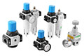
VPC provides several air preparation unit product families, including AC-series FRL assemblies and filter-regulator combinations. Review the exact series datasheet and configuration options before specifying an order.
Send VPC your inlet pressure, required downstream pressure, peak airflow, air-quality requirements and connection details. Our team can help review suitable air preparation configurations.
Explore VPC Air Preparation Units →Start with peak simultaneous airflow and the required operating pressure. Then verify candidate flow-performance curves, allowable pressure drop, piping connections and air-quality requirements.
An FR unit includes a filter and regulator; an FRL unit adds a lubricator. Choose based on whether the connected equipment requires externally lubricated compressed air.
Yes. Internal design, filtration stages, regulator performance and test conditions all influence flow capacity. Port size alone does not establish usable airflow.
Downstream pressure can fall during high consumption, leading to slower cylinder movement, reduced actuator force or less consistent machine operation.
No. Many cylinders are rated for non-lubricated air. Always follow the actual cylinder and valve manufacturers' requirements.
No. A conventional filter can separate certain liquid contaminants, but it cannot replace a dryer when the application requires control of water vapor or pressure dew point.
Yes, provided the unit and the downstream network can deliver the maximum simultaneous airflow while maintaining the required pressure and air quality.
Provide inlet pressure, operating pressure, peak flow, port thread, filtration and lubrication requirements, preferred drain type, environment and installation dimensions.



 English