Views: 8 Author: Site Editor Publish Time: 2026-10-28 Origin: Site


A pneumatic gripper uses compressed air to open and close its jaws. The solenoid valve controls where that air goes. Choosing the wrong valve can cause slow movement, unreliable operation or unexpected behavior when power is lost.
So which solenoid valve should you use? Start with the gripper type, then check the required speed, working pressure, electrical connection and failure behavior.
Quick answer: A 3/2-way valve is a common choice for a single-acting gripper. A 5/2-way valve is a common starting point for a double-acting gripper. The final choice must match the actual gripper and machine circuit.


First, check whether the gripper uses compressed air for one direction or both directions.
| Gripper Type | How It Works | Common Valve Choice |
|---|---|---|
| Single-acting pneumatic gripper | Air moves the jaws one way; a spring or other mechanism returns them. | 3/2-way pneumatic valve |
| Double-acting pneumatic gripper | Air controls both opening and closing. | 5/2-way pneumatic valve |
| Special or integrated control | Operation depends on the built-in mechanism. | Check the gripper manual and circuit. |
One air-driven direction, usually with a spring return. A 3/2 solenoid valve can supply and exhaust the working chamber.
Two air-driven directions. A 5/2 valve switches supply and exhaust between the two working ports.
For a single-acting gripper cylinder: air might close the jaws while a spring opens them—or the opposite. Always check whether the gripper is spring-open or spring-closed and verify the valve’s normal position.
For a double-acting gripper cylinder: a 5/2 valve typically sends air to one chamber while the other chamber exhausts. When the valve switches, the flow paths reverse. Which port opens or closes the jaws depends on the gripper and tubing layout.
After choosing a valve function, decide how the valve should respond when the electrical signal is removed.
| Valve Type | Typical Behavior | What to Check |
|---|---|---|
| Single-solenoid, spring-return 5/2 | Returns to its normal valve position when the coil is switched off. | Does the normal flow path command opening or closing? |
| Double-solenoid, bistable 5/2 | Normally stays in its last switched position when power is removed. | What happens if compressed air is also lost? |
Safety reminder: Keeping the valve in its last position does not mean the gripper can hold a workpiece indefinitely. Leaks and loss of air pressure can reduce gripping force.
Will a larger valve always make the gripper faster? No. Airflow must be sufficient, but the entire air path affects speed.
Actual supply pressure at the machine
Valve flow capacity at the relevant pressure conditions
Air tube length and internal diameter
Fittings, speed controllers and exhaust silencers
Gripper size, jaws and attached fingers
For example, a high-flow solenoid valve may still give slow movement if the air tube is too narrow or the exhaust is heavily restricted.
1Confirm the operating pressure is within the gripper’s specified range.
2Check valve flow using the actual pressure and flow conditions.
3Avoid unnecessarily long or narrow tubing.
4Check the exhaust path and adjust speed controls for smooth motion.
5Measure opening and closing times separately with the real workpiece.
Do not simply increase pressure or select the largest valve. Excessive speed can cause hard impacts at the gripper stops or against the part.
A typical double-acting gripper circuit includes a compressed-air supply, pressure regulator, 5/2-way valve, two working tubes, a gripper and optional speed controls and sensors.
1PLC sends a command. The control system switches the solenoid valve.
2Valve redirects airflow. One chamber is supplied while the other exhausts.
3Gripper moves. The jaws open or close according to the chamber pressurized.
4Sensor reports position. A position sensor can tell the PLC when a set jaw position is reached.
Important: A jaw-position sensor reports position. It does not directly prove gripping force or confirm that the workpiece is securely held.
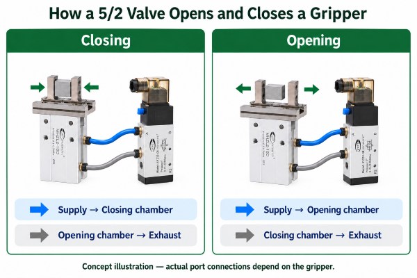
The valve may return to its normal position or retain its previous position, depending on its design. This can affect jaw movement.
Pressure may decrease due to loss of supply or leakage, even when the valve stays in the same position.
When a falling part could cause injury or damage, the machine designer must define the required safe response and verify the complete circuit. Depending on the risk assessment, additional measures may include a suitable spring-assisted gripper, a validated pressure-retention design or mechanical support.
Never assume: A closed-center valve or a double-solenoid valve alone guarantees safe load holding.
| Check | What to Confirm |
|---|---|
| 1. Gripper type | Single-acting or double-acting? |
| 2. Valve function | 3/2 or 5/2? What is the valve’s normal position? |
| 3. Pressure and airflow | Do they meet the gripper and cycle requirements? |
| 4. Electrical connection | Do coil voltage, connector and control signal match? |
| 5. Actual performance | Has the full circuit been tested with real parts and failure conditions? |
Also verify port threads, installation space, tubing routes and the exact product order codes. Final performance should be checked on the assembled machine.
Check pressure, valve flow, tubing restrictions, speed controls and exhaust paths before replacing the valve.
Verify the gripper ports, valve symbol, tubing connections and PLC switching sequence.
Review gripping-force requirements, finger length, contact surfaces and actual operating pressure. Test with the real workpiece.
For more on selecting the gripper itself, see the Pneumatic Gripper Selection Guide.
VPC Pneumatic offers pneumatic grippers, solenoid valves and related components for industrial automation. To evaluate a suitable option, share your:
Gripper model or datasheet
Operating air pressure and required cycle time
Coil voltage and connector requirements
Current valve code, if available
Workpiece and application details
Our team can review candidate components for further technical confirmation. Exact model compatibility, specifications and availability must be verified against current product documentation.
No. Valve function is only the starting point. Airflow, pressure, port arrangement, switching behavior and electrical interface must also fit.
Yes. It is commonly used with single-acting grippers that have one pneumatic working connection.
No. Tubing, fittings, exhaust restrictions, supply pressure and the gripper itself may limit speed.
A position sensor can confirm a detected jaw position, but it cannot directly prove that the part is securely held.
It depends on the valve design, its normal position, the gripper mechanism and air supply. Power-loss and air-loss conditions must be tested separately.
There is no universal best choice. Start with the gripper type, then check pressure, airflow, electrical requirements, cycle time and failure behavior.



 English