Views: 15 Author: Site Editor Publish Time: 2026-09-03 Origin: Site


A pneumatic gripper should be selected from the part and the machine movement, not from bore size alone. First check the part shape, weight, surface, gripping direction, acceleration, available air pressure, and where the fingers touch the part.
Then confirm three things: enough usable grip force, enough jaw travel to load and release every part size, and a safe response if air pressure is lost. One catalog number cannot prove the complete setup will work.
| Workpiece or machine need | Common starting point | What must still be checked |
|---|---|---|
Prismatic parts with two accessible sides | Two-jaw parallel gripper | External or internal grip, finger overhang, stroke, and part tolerance |
Round or cylindrical parts that need centering | Three-finger centric gripper | Diameter range, centering requirement, surface damage, and jaw profile |
Several part sizes on one station | Wide-opening or long-stroke gripper | Extra travel time, finger mass, guidance, and closing impact |
Very limited vertical installation space | Low-profile parallel gripper | Mounting rigidity, available stroke, sensor position, and hose routing |
Jaws must swing clear of a fixture | Angular or 180-degree angular gripper | Envelope through the full motion, opening angle, and collision clearance |
Vertical transfer or a dropped part creates a hazard | Fail-safe design, not just a larger gripper | Spring option, check valve or pressure retention, part support, and risk assessment |
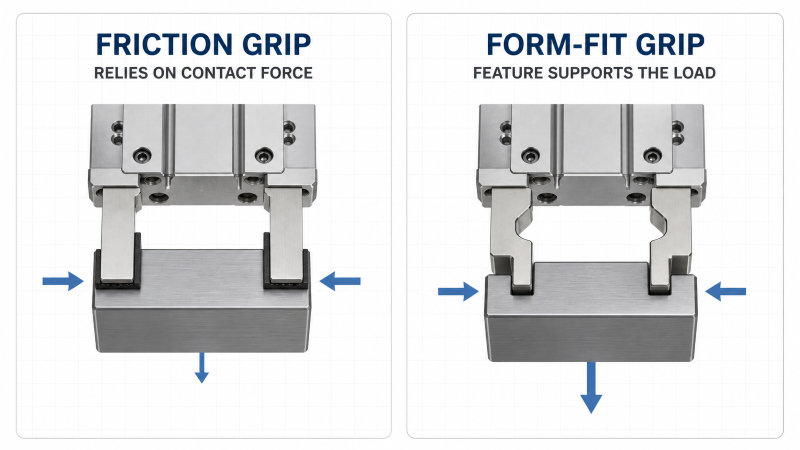
Flat pads rely mainly on friction; shaped fingers can support the load through the part geometry.
The fingers change how the gripper behaves. Long fingers put more leverage on the jaw guide. Heavy fingers are harder to start and stop. Smooth or oily parts are also easier to slip than dry, rough parts.
Before choosing a model, collect:
Part weight and smallest/largest gripping size.
Shape, material, surface, and center of gravity.
External or internal grip and allowed contact area.
Machine direction, acceleration, and cycle rate.
A drawing or clear photo of the real part.
Finger shape also matters. Flat pads depend mainly on friction. Shaped fingers can catch a shoulder or groove and support the load mechanically. Fragile, polished, coated, or thin-walled parts may need softer pads and a larger contact area, even when the gripper has enough force.
Grip force must cover more than the part weight. Fast starts, stops, vibration, impact, changing air pressure, and a slippery surface can all make the part harder to hold.
Check these four inputs:
The load created by the part's weight.
The extra load from acceleration and impact.
How much friction the contact surface can provide.
A safety margin for pressure changes, wear, and uncertainty.
With two opposed fingers, both contact points can help hold the part only when they touch correctly and share the load. Poor alignment or uneven contact reduces the usable force.
Before comparing two catalog force values, confirm:
Total force or force per jaw.
Opening force or closing force.
Test air pressure.
Finger length and gripping-point distance.
SMC, Festo, and SCHUNK publish these conditions because usable force changes when the contact point moves farther from the jaw face.
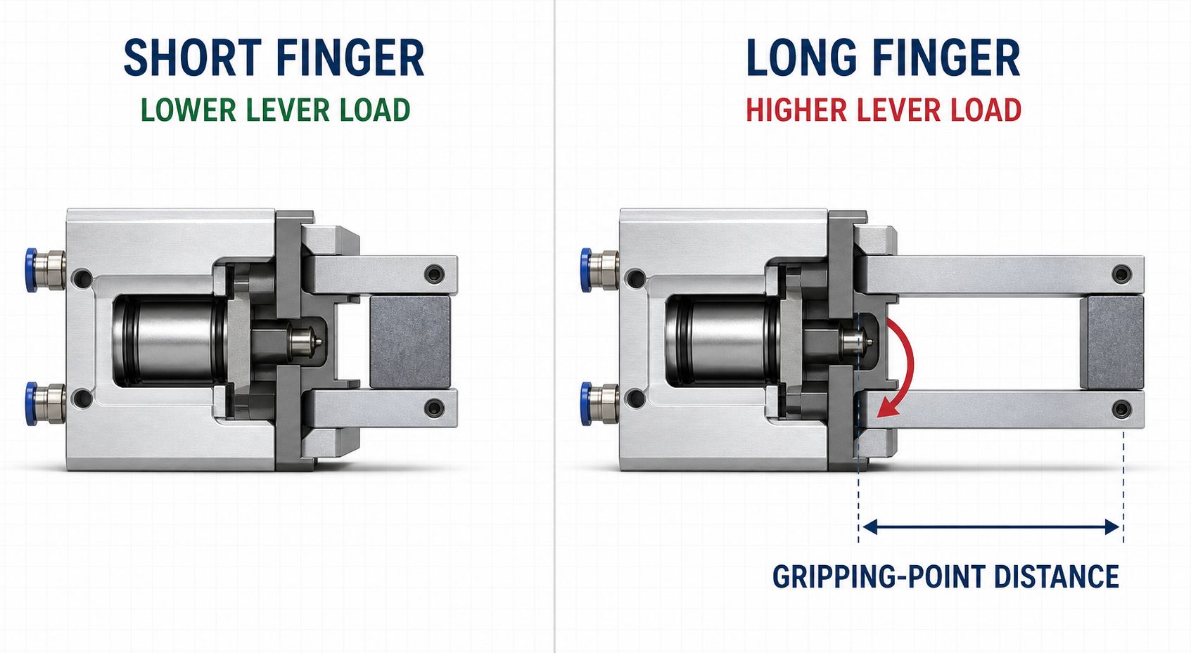
A longer finger increases leverage and guide load at the same gripping point.
A long finger works like a long lever. It puts more load on the jaw guide and can reduce the load the gripper can safely hold at the fingertip. This is why custom fingers can cause sticking, early wear, or loss of usable force even when the gripper body has not changed.
To reduce this risk:
Keep fingers short and light.
Place the contact point close to the jaw face.
Check the maker's permitted gripping-point range.
If long fingers are unavoidable, reduce acceleration and verify finger stiffness, force, and allowable guide load.
Jaw stroke is the movement needed to load, grip, and release the full part-size range. Check the smallest and largest gripping sizes, part tolerance, finger shape, loading clearance, and whether the catalog gives stroke per jaw or total stroke.
Too little stroke: incomplete contact, hard loading, or failure to release the largest part.
Too much stroke: longer cycle time, more impact, and a larger machine envelope.
For several part sizes, compare a wide-opening gripper with interchangeable fingers. The simpler option is often faster and more rigid.
Repeatability tells you how consistently the jaws return to the same position under stated test conditions. It is not the same as absolute position accuracy, and it does not prove that the whole tool will place the part within the same tolerance.
The final part position also depends on:
Finger machining and bending.
Jaw-guide clearance and mounting rigidity.
Part-size and surface variation.
Air-pressure stability and sensor switching point.
If another fixture locates the part, very tight jaw repeatability may not be necessary. If the gripper centers the part for inspection or assembly, centering accuracy becomes critical.
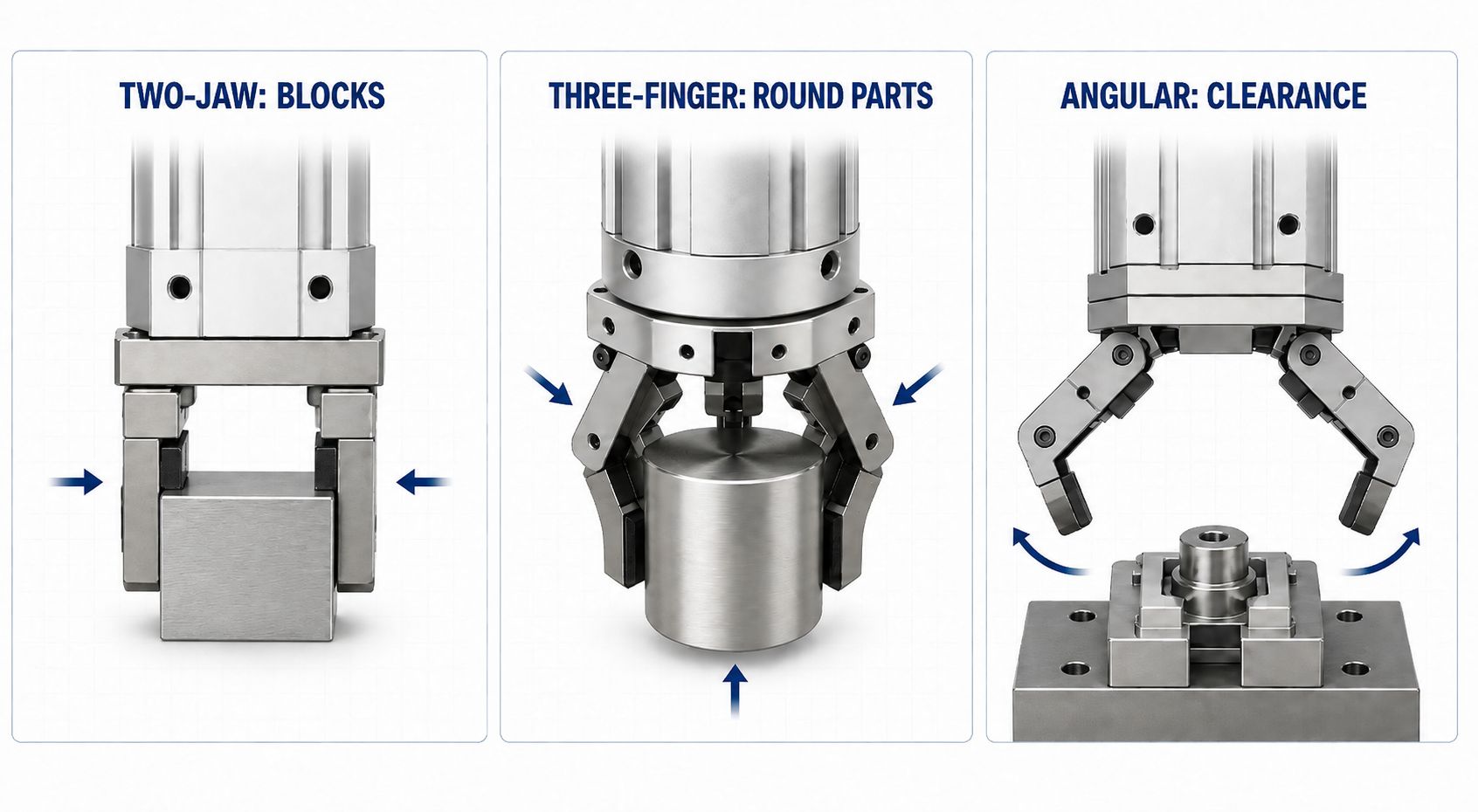
Choose the gripper type from the workpiece shape and required clearance.
Two-jaw parallel grippers are the usual starting point for blocks, plates, connectors, housings, and many machined components. The jaws remain parallel through the stroke, which simplifies straight fingers and external or internal gripping. VPC's current range includes MHZ2 and HFZ compact parallel families.
Three-finger centric grippers suit round, cylindrical, and some irregular parts when automatic centering is valuable. VPC's MHS3 family is positioned for this type of workpiece. A three-finger layout does not eliminate the need to check diameter range, finger profile, surface pressure, and centering requirements.
Wide-opening and long-stroke grippers are useful when the station handles a large dimensional range or must clear a feature before closing. VPC lists MHZL2 and MHL2 families for wide-opening applications. The trade-off is usually a larger envelope and more moving mass, so cycle time and custom finger loads deserve extra attention.
Low-profile grippers solve packaging constraints where overall height is more restrictive than width. VPC's MHF family provides short, middle, and long-stroke arrangements. Verify hose, sensor, mounting, and finger access in the actual machine layout rather than comparing body height alone.
Angular grippers rotate the fingers away from the part and can create useful loading clearance. VPC lists HFY angular and MHW2 180-degree angular families. Check the entire swept envelope; an open jaw can collide with a fixture even when the closed position fits.
The catalog opening or closing time usually covers only the gripper body under stated test conditions. The machine cycle also includes:
Solenoid-valve response.
Air filling and exhausting through the tubing.
PLC and sensor delay.
Robot movement and custom-finger weight.
For a fast station, test the complete air circuit. Short tubing, enough valve flow, lighter fingers, and controlled exhaust may improve response more than a larger gripper. Raising pressure will not fix an undersized valve or restrictive tube; it may only increase impact and wear.
A jaw-open or jaw-closed sensor confirms position, not grip force. If the machine must confirm that a part is present, it may need an intermediate-position sensor, an external sensor, machine vision, or another check. Also confirm cable direction, connector type, and teach position before finalizing the tool.
For vertical handling or any part that could injure someone or damage equipment if dropped, pressure loss must be treated as a machine-safety issue.
Possible measures include a spring-assisted gripper, pressure-retention circuit, check valve, mechanical support, or part catcher.
The correct choice depends on the risk assessment.
More grip force alone is not a complete fail-safe solution.
Dust, chips, coolant, washdown, corrosive atmosphere, welding spatter, and temperature can change the suitable gripper and maintenance interval. Confirm whether the guide and seals are protected for the real environment. Keep the air supply within the specified filtration and lubrication requirements, avoid side-loading the jaws, and inspect finger fasteners and contact pads as part of preventive maintenance.
Cycle-life statements are only meaningful when the load, pressure, stroke, finger mass, gripping point, speed, environment, and maintenance conditions are stated. For high-volume OEM programs, request application-specific validation and agree on the test conditions before treating a cycle count as an acceptance criterion.
Application need | VPC family to evaluate | Required final verification |
|---|---|---|
Compact parallel grip | MHZ2, HFZ | Stroke, force curve, gripping point, bore, sensor, and mounting |
Wide opening | MHZL2, MHL2 | Part range, total travel, finger mass, opening time, and envelope |
Low-profile installation | MHF | Body height, stroke option, mounting access, and sensor routing |
Round-part centering | MHS3 | Diameter range, centering tolerance, contact pressure, and finger geometry |
Angular clearance | HFY, MHW2 | Opening angle, swept envelope, force at contact, and collision clearance |
High holding demand | MHT2 candidate configuration | Exact mechanism, pressure range, holding method, safety requirement, and current datasheet |
This table is an application starting point, not a declaration of direct interchangeability with another brand. A replacement decision must compare mounting dimensions, port positions, jaw interface, stroke, force curve, sensor, pressure range, and machine risk.
Send these details for selection or a quotation:
Part drawing or clear photos, weight, material, and surface.
Smallest and largest gripping dimensions.
External or internal grip and machine orientation.
Acceleration, target cycle time, and available air pressure.
Finger length, weight, and gripping-point distance.
Environment, sensor needs, pressure-loss safety needs, mounting, target model, and quantity.
1. Can I select a pneumatic gripper by workpiece weight alone?
No.
Weight is only the starting point.
Also check gripping direction, acceleration, friction, finger length, air pressure, impact, and drop risk.
2. Is a three-finger gripper always better for round parts?
It is often easier to center cylindrical parts with three fingers, but two profiled jaws may be faster, simpler, or more compact. The required centering tolerance and part geometry decide the better option.
3. Does a larger jaw stroke make a gripper safer?
Not necessarily. Extra stroke can increase travel time, impact, and envelope. The right stroke clears the full tolerance range and permits reliable loading and release without unnecessary motion.
4. Can repeatability be used as positioning accuracy?
No. Repeatability describes consistency under defined conditions. Absolute position, centering, finger deflection, part variation, and tooling tolerance must be evaluated separately.
5. Can an auto switch confirm that the part is securely held?
A switch can confirm jaw position or a taught position, but it does not directly measure gripping force. Critical applications may need additional pressure, position, vision, or force verification.
6. Can a VPC gripper replace an SMC, Festo, or other brand model?
Possibly, but only after a model-by-model check.
Compare mounting, jaw interface, ports, stroke, and force conditions.
Confirm sensors, pressure range, dimensions, and machine risk.
Similar appearance or bore size is not enough.
7. What usually causes premature gripper wear?
Long or heavy fingers.
Side load, hard impact, or poor guidance.
Dust, chips, coolant, or other contamination.
Pressure or cycle rate outside the validated conditions.
8. What is the fastest way to obtain a reliable recommendation?
Send the part drawing, weight, and size range.
State the gripping direction, acceleration, cycle time, and air pressure.
Include the finger idea, environment, sensor needs, and current model.
This prevents selection from bore size or one catalog force value alone.



 English