Views: 15 Author: Site Editor Publish Time: 2026-08-06 Origin: Site


VPC Pneumatic Official Spanish Website: https://vpc-pneumatic.mx/
1. PF2A or PF3W: which flow switch should you choose?
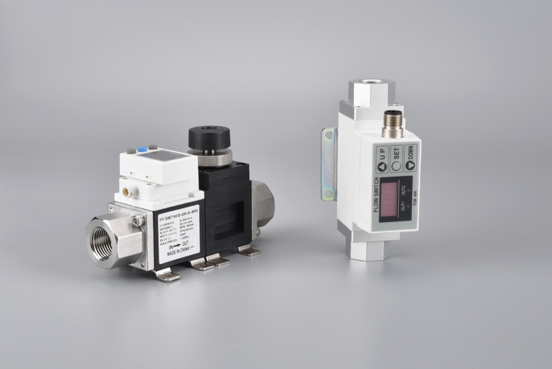
Choose PF2A-type equipment for compressed air or nitrogen. Choose PF3W-type equipment for water or an explicitly permitted coolant. The two families solve a similar monitoring task, but they are not interchangeable because the medium, sensing design, wetted materials and installation rules differ.
After the medium is confirmed, compare minimum, normal and peak flow, operating pressure, temperature, pressure loss, port, output, connector and mounting space. A family name alone is not enough to approve a replacement.
2. PF2A vs PF3W at a glance
| Decision point | PF2A Digital Flow Switch | PF3W Digital Flow Switch |
| Primary medium | Compressed air; nitrogen where the exact model permits it | Water; specified coolant only when fluid compatibility is documented |
| Main buyer task | Measure consumption, confirm air flow, screen abnormal demand and support low-flow interlocks | Confirm cooling flow, protect heat-removal circuits and support low-flow interlocks |
| Reference range in reviewed SMC literature | 1-10 L/min through 50-500 L/min | 0.5-4 L/min through 50-250 L/min for referenced integrated-display models |
| Installation reference | At least 8D on the inlet side in the reviewed PF2A/PF2A7 material | Model-specific; several referenced models use at least 8 cm, with 11 cm for certain 100 and 250 L/min types |
| Critical risk | Wrong reference flow, oil/water contamination, short inlet, thread or PLC mismatch | Fluid incompatibility, trapped air, pressure loss, freezing, short inlet or PLC mismatch |
| Replacement status | Compatible only after dimensional, electrical and performance checks | Compatible only after fluid, dimensional, electrical and performance checks |
Step 1: identify the medium before comparing models
For compressed air, record moisture, oil carryover, particles and the reference condition used for L/min. A flow value without a stated reference condition can be misleading when comparing two gas-flow devices.
For water or coolant, record the full fluid name, glycol type and concentration, additives, viscosity, temperature and cleanliness. “Coolant” is not one universal medium; seals and wetted materials must be checked against the actual formulation.
| Application | Model | Do not proceed until |
| Machine compressed-air consumption | PF2A-type | Minimum, normal and peak flow are known under the same reference condition |
| Nitrogen purge confirmation | PF2A-type | The exact order code explicitly permits nitrogen |
| Chiller or machine-tool water loop | PF3W-type | Water quality, temperature and pressure-loss budget are known |
| Water-glycol cooling loop | PF3W-type | Glycol formulation, concentration, viscosity and wetted-material compatibility are confirmed |
| Oil or an unlisted chemical | Neither by assumption | A sensor family specifically documented for that fluid is selected |
Step 2: compare the PF2A air-flow requirements
The official PF2A literature reviewed for this page lists air and nitrogen. Its reference family covers several rated-flow bands and model-dependent Rc, NPT and G thread options.
The supplied PF2A7 manual and the official PF2A catalog both specify an inlet straight section of at least eight times the piping diameter. The official catalog warns that the reading can deviate by 5% F.S. or more when that straight section is not provided.
Do not replace this model-specific evidence with a generic 10D upstream and 5D downstream rule. Confirm the installation requirement from the selected order code.
Step 3: compare the PF3W water-flow requirements
The reviewed PF3W catalog lists water and ethylene-glycol aqueous solution with viscosity up to 3 mPa.s, provided that the fluid does not corrode or damage the wetted materials. That condition is more important than the generic word “coolant.”
The same reference family lists 0-90 ℃ fluid temperature without freezing or condensation, 0-1 MPa operating pressure, 1.5 MPa proof pressure and IP65 for the referenced standard models. These are source-family values, not automatic VPC claims.
PF3W straight-pipe requirements are model-specific. The reviewed integrated family uses at least 8 cm in several cases and at least 11 cm for certain higher-flow types. PVC-piping versions use different geometry, so one universal length should not be published.
Step 4: size the flow range from the real process
Record minimum, normal and peak flow. The selected range must capture the low-flow decision point without saturating at the process peak.
Do not use a generic "operate at 60-80% of range" statement as a specification. Resolution, accuracy, display range and response depend on the exact model and the process requirement.
| Parameter | PF2A check | PF3W check |
| Flow basis | State the gas reference condition and units | State actual liquid flow and viscosity condition |
| Pressure | Pressure at the sensor, not only compressor discharge | Operating pressure plus available differential pressure |
| Pressure loss | Check restrictions in filter, tubing and sensor | Check sensor and optional adjustment-valve loss at peak flow |
| Temperature | Gas and ambient limits from exact datasheet | Fluid and ambient limits; prevent freezing and condensation |
| Port | Thread standard, size, flow direction and 8D space | Thread/pipe standard, size, direction and model-specific inlet space |
Step 5: match outputs, wiring and PLC logic
Both source families include model-dependent NPN or PNP switch outputs and analog options. The exact functions can change with the suffix, so the full order code is required.
3. Common faults: air side vs water side
| Symptom | PF2A-type first checks | PF3W-type first checks |
| Unstable reading | Short inlet, nearby elbow/valve, pulsation, contamination | Air bubbles, pulsating pump, short inlet, turbulence |
| Reading too low | Wrong direction, restriction, pressure drop, wrong range | Wrong direction, blocked line, air lock, insufficient pump pressure |
| Flow when equipment is idle | Leakage, bypass or zero-clear condition | Bypass, gravity circulation or valve leakage |
| No PLC signal | Supply, common, NPN/PNP, pinout, scaling | Supply, common, NPN/PNP, pinout, scaling |
| Leak at port | Thread mismatch, sealant or mechanical stress | Thread mismatch, torque, seal or fluid incompatibility |
FAQ
1. Can PF2A measure water?
No. The reviewed PF2A family is documented for air and nitrogen. Use a liquid-flow family documented for the actual water or coolant.
2. Can PF3W measure compressed air?
No. The reviewed PF3W family is designed for water and permitted coolant. Gas-flow measurement requires a documented gas sensor.
3. Does every PF2A need 8D?
The reviewed PF2A and supplied NPF2A7 material use an 8D inlet rule. Always check the manual for the exact selected order code.
4. Does every PF3W need 8 cm?
No. The required straight length changes by model and piping. The reviewed literature also uses 11 cm for certain higher-flow types.
The PF2A vs PF3W decision is primarily a medium decision: PF2A for compressed air or permitted nitrogen, PF3W for water or a documented coolant. Correct selection then depends on real flow, pressure, temperature, pressure loss, piping, signal and mechanical fit.
VPC can evaluate alternative designs for the Asian market upon receipt of the complete existing code and application data. For specific inquiries regarding VPC order codes, dimensions, certifications, IO-Link support, and commercial availability, please contact VPC Pneumatic.



 English