| Working medium: | |
|---|---|
| Working temperature: | |
| Proof pressure: | |
| Accuracy: | |
Product Specification
1. 3-color/2-screen display.
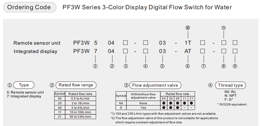
2. Integrated display type, Separate monitor type, and PVC piping type.
3. Reduced required piping space.
4. Rotatable display: Counterclockwise 90°, Clockwise 225°. Display can be rotated in increments of 45° to suit the installation conditions.
5. Easy operation, improved visibility. New model PF3W721-14- -M. (Flow rate set from 20-350L/min).
Product Description
| Model | PF3W704 | PF3W720 | PF3W740 | PF3W711 | PF3W721 | |
| Working medium | Water and ethylene glycol aqueous solution (with viscosity of 3mPa·s [3 cP] or less) | |||||
| Detection method | Karman vortex | |||||
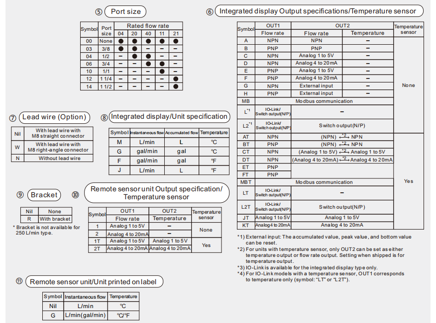
| Rated flow range | 0.5 to 4 L/min | 2 to 16 L/min | 5 to 40 L/min | 10 to 100 L/min | 50 to 250 L/min | |
| Display flow range *1) | 0.35 to 5.5 L/min | 1.7 to 22.0 L/min | 3.5 to 55.0 L/min | 7 to 140.0 L/min | 20 to 350.0 L/min | |
| Set flow range | 0.35 to 5.5 L/min | 1.7 to 22.0 L/min | 3.5 to 55.0 L/min | 7 to 140.0 L/min | 20 to 350.0 L/min | |
| Smallest settable increment | 0.01 L/min | 0.1 L/min | 0.1 L/min | 1 L/min | 2 L/min | |
| Conversion of accumulated pulse (Pulse width: 50ms) | 0.05 L/pulse | 0.1 L/pulse | 0.5 L/pulse | 1 L/pulse | 2 L/pulse | |
| Fluid temperature | 0 to 90°C (No freezing or condensation) | 0 to 70°C (No freezing or condensation) | ||||
| Display unit | Instantaneous flow: L/min, Accumulated flow: L | |||||
| Accuracy | Display value: ±3% F.S. Analog output: ±3% F.S. | |||||
| Repeatability | ±2% F.S. *2) | |||||
| Temperature characteristics | ±5% F.S. (25°C standard) | |||||
| Operating pressure | 0 to 1 MPa | |||||
| Proof pressure | 1.5 MPa | |||||
| Pressure loss (Without flow adjustment valve) | 45 kPa or less at the maximum flow | 60 kPa or less at the maximum flow | ||||
| Accumulated flow range *3) | 99999999.9 L | 999999999 L | ||||
| By 0.1 L | By 0.5 L | By 1 L | ||||
| Switch output | NPN or PNP open collector output | |||||
| Max. load current | 80 mA | |||||
| Max. applied voltage | DC 28 V | |||||
| Internal voltage drop | NPN: 1 V or less (at load current of 80 mA); PNP: 1.5 V or less (at load current of 80 mA) | |||||
| Response time *2),4) | 0.5 s / 1 s / 2 s | |||||
| Output protection | Short-circuit protection | |||||
| Output mode | Flow rate | Select from Hysteresis, Window comparator, Accumulated output, or Accumulated pulse output modes. | ||||
| Temperature | Select from Hysteresis mode or Window comparator mode | |||||
| Analog output | Response time *5) | 0.5 s / 1 s / 2 s (linked with the switch output) | ||||
| Voltage output | Output voltage: 1 to 5 V; Output impedance: 1 kΩ | |||||
| Current output | Output current: 4 to 20 mA; Max. load impedance: 300 Ω for DC 12 V, 600 Ω for DC 24 V | |||||
| Hysteresis | Variable | |||||
| External input | Voltage free input: 0.4 V or less (Reed or Solid state), input for 30 ms or longer | |||||
| Display method | 2-screen display (Main screen: 4-digit, 7-segment, 2-color; Red/Green Sub screen: 6-digit, 11-segment, White) | |||||
| Indicator light | Output 1, Output 2: Orange | |||||
| Power supply voltage | DC 12 to 24 V ±10% | |||||
| Current consumption | 50 mA or less | |||||
| Environment | Enclosure | IP65 | ||||
| Working temperature | 0 to 50°C (No freezing or condensation) | |||||
| Working humidity | Operation, Storage: 35 to 85% R.H. (No condensation) | |||||
| Withstand voltage *6) | AC 1000 V for 1 minute between terminals and housing | |||||
| Insulation resistance | 50 MΩ or more (DC 500 V measured via megohmmeter) between terminals and housing | |||||
| Standards and regulations | CE marking (EMC directive/RoHS directive), UL (CSA) | |||||
| Wetted parts material | PPS, FKM, SCS13, SUS304; Non-grease | |||||
| Piping port size *7) | 3/8 | 3/8, 1/2 | 1/2, 3/4 | 3/4, 1 | 1 1/4, 1 1/2 | |
*1) When the actual flow rate is less than the minimum display flow range , the display will show "0.00 ", "0.0 " or "0 ".
*2) If 0.5s is selected for the response time of the switch output , the repeatability will be ±3% F.S.
*3) Cleared when the power supply is turned off. The hold function can be selected. (Intervals of 2 or 5 minutes can be selected.) If the 5-minute interval is selected , the life of the memory element (electronic parts) is limited to 1 million times .(If energized for 24 hours , life is calculated as 5 minutes ×1 million = 5 million minutes = about 9 .5 years .)
Therefore , if using the hold function , calculate the memory life for your operating conditions , and use within this life .
*4) The response time when the set value is 90% in relation to the step input (The response time is 7 s when it is output by the temperature sensor.)
*5) The response time until the set value reaches 90% in relation to the step input (The response time is 7 s when it is analog output by the temperature sensor.)
*6) With a temperature sensor, the withstand voltage is 250 VAC.
*7) When the piping diameter or piping passage is restricted , the specifications may not be satisfied.
*8) Products with tiny scratches , marks , or display color or brightness variations which do not affect the performance of the product are verified as conforming products .
When only optional parts are required , order with the part numbers listed below.
| Description | Part NO. | Qty. | Note | |
| Bracket* | ZS-40-K | 1 | For PF3W704/720/504/520 | With 4 tapping screws (3×8) |
| ZS-40-L | 1 | For PF3W740/540 | With 4 tapping screws (3×8) | |
| ZS-40-M | 1 | For PF3W711/511 | With 4 tapping screws (4×10) | |
| Lead wire with M8 connector | ZS-40-A | Lead wire length: 3m | ||
* For units with flflow adjustment valve, 2 brackets are required.
(PF3W704/720/740)
| Symbol | A | B | C |
| Voltage output | 1V | 1.5V | 5V |
| Current output | 4mA | 6mA | 20mA |
(PF3W711)
| Symbol | A | B | C |
| Voltage output | 1V | 1.4V | 5V |
| Current output | 4mA | 5.6mA | 20mA |
(PF3W721)
| Symbol | A | B | C |
| Voltage output | 1V | 1.8V | 5V |
| Current output | 4mA | 7.2mA | 20mA |
| Model | Rated flow [L/min] | |
| Mini. | Max. | |
| PF3W704/504 | 0.5 | 4 |
| PF3W720/520 | 2 | 16 |
| PF3W740/540 | 5 | 40 |
| PF3W711/511 | 10 | 100 |
| PF3W721/521 | 30 | 250 |

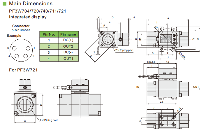
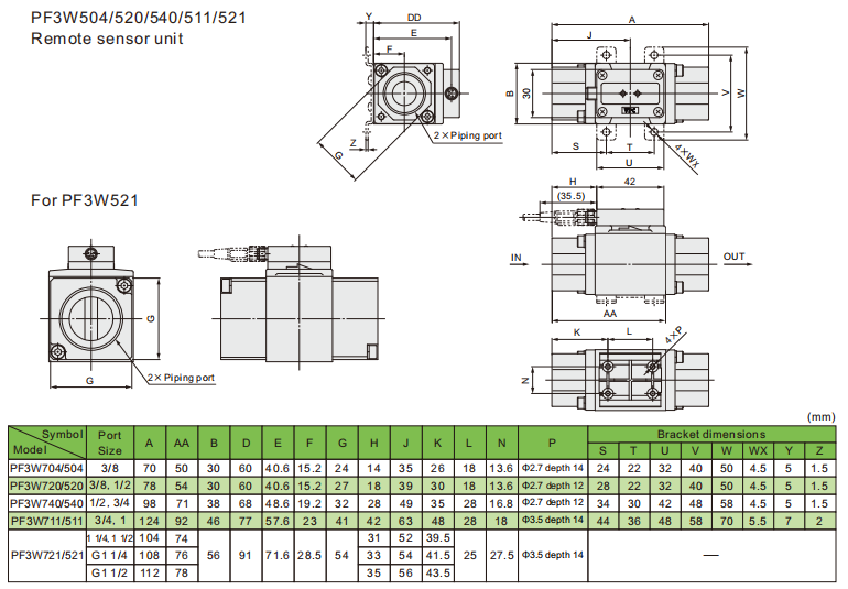
Main Dimensions


 English