sales@vpc-pneumatic.com 0086-13989308920 


| Body material: | |
|---|---|
| Bore: | |
| Stroke range: | |
| Quality warranty: | |
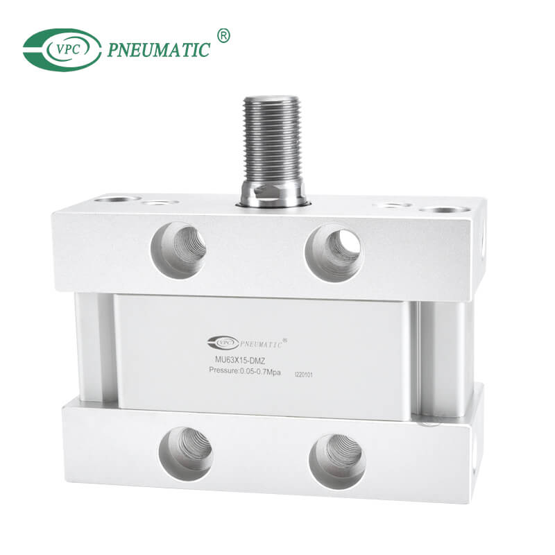
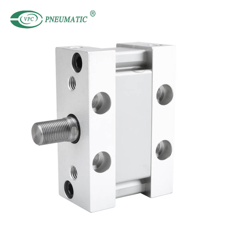
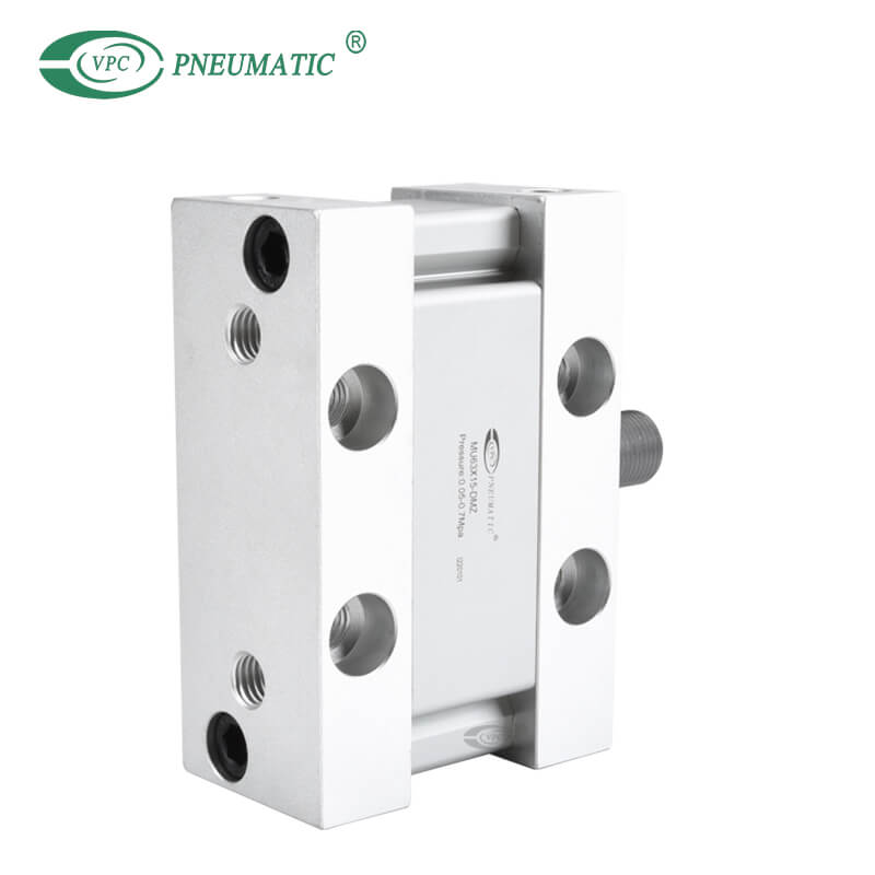
Product Description
1. Plate type cylinder design for ultra compact, oval piston design for non-rotation and space saving.
2. Possible to mount without brackets.
3. There are magnetic switch slots on sides for the cylinder body, which is convenient to install inducting switch.
4. The internal diameter of the body is treated with rolling followed by the treatment of hard anodizing, forming an excellent abrasion resistance and durability.
5. The seal of piston adopts heterogeneous two-way seal structure. It has compact dimension and the function of oil reservation.
6. Strokes up to 300mm.
7. Installing accessories with various specifications is optional.


※ Double force and multi-force cylinders are customized.
※ If a built-in magnet cylinder without an auto switch is required,there is no need to enter the symbol for the auto switch.
Example: MDUL32-30DZ
Product Specifications
| Bore(mm) | 25 | 32 | 40 | 50 | 63 |
| Working medium | Air | ||||
| Acting type | Double acting, Single rod | ||||
| Guaranteed pressure | 1.05MPa | ||||
| Max. Working pressure | 0.7MPa | ||||
| Mini. Working pressure | 0.05MPa | ||||
| Working temperature | -10 to 60℃ | ||||
| Lubrication | Not required (Non-lube) | ||||
| Piston speed | 50 to 500 mm/s | ||||
| Tolerance of stroke | +1.4 0 | ||||
| Cushion Type | Rubber bumper | ||||
| Mounting | Foot, Rod flange, Head flange, Single clevis, Double clevis | ||||
| Rod end configuratio | Rod end male thread, Rod end female thread | ||||
| Allowable rotational torque | 0.25 N·m | 0.55 N·m | 1.25 N·m | 2.0 N·m | |
| Rod non-rotating accuracy | ±1° | ±0.8° | ±0.5° | ||
| Size (mm) | Standard stroke (mm) | Max. manufacturable stroke(mm) |
| 25, 32, 40, 50, 63 | 5, 10, 15, 20, 25, 30, 35, 40, 45, 50, 75, 100, 125, 150, 175, 200, 250, 300 | 300 |
※ Other intermediate strokes can be manufactured upon receipt of order. Please contact VPC.
※ Strokes longer than 300 mm are not available.
Main Dimensions


(N)
| Size | Rod size (mm) | Operating direction | Piston area (mm²) | Operating pressure (Mpa) | |||||
| 0.2 | 0.3 | 0.4 | 0.5 | 0.6 | 0.7 | ||||
| 25 | 12 | OUT | 491 | 98 | 147 | 196 | 246 | 295 | 344 |
| IN | 378 | 76 | 113 | 151 | 189 | 227 | 265 | ||
| 32 | 14 | OUT | 804 | 161 | 241 | 322 | 402 | 482 | 563 |
| IN | 650 | 130 | 195 | 260 | 325 | 390 | 455 | ||
| 40 | 16 | OUT | 1257 | 251 | 377 | 503 | 629 | 754 | 880 |
| IN | 1056 | 211 | 317 | 422 | 528 | 634 | 739 | ||
| 50 | 20 | OUT | 1963 | 393 | 589 | 785 | 982 | 1178 | 1374 |
| IN | 1649 | 330 | 495 | 660 | 824 | 989 | 1154 | ||
| 63 | 20 | OUT | 3117 | 623 | 935 | 1247 | 1559 | 1870 | 2182 |
| IN | 2803 | 561 | 841 | 1121 | 1402 | 1682 | 1962 | ||
※ Note) Theoretical output (N) =Pressure (MPa) × Piston area (mm²)
Product FAQ
Q1: What is compact cylinder?
A: Also known as short-stroke cylinders, compact pneumatic cylinders are designed for installation in confined spaces. Single-acting, double-acting, magnetic, non-magnetic and non-rotating versions are available. Click here for our various compact pneumatic cylinders.
Q2: How does a compact cylinder work?
A pneumatic cylinder is a mechanical device that converts compressed air energy into a reciprocating linear motion. A double-acting cylinder uses compressed air to move a piston in and out, while a single-acting cylinder uses compressed air for one-way movement and a return spring for the other.
Q3: How do I increase the pressure in my pneumatic cylinder?
A: Another way to increase or decrease the forces generated by the cylinder is to choose a cylinder with either a more significant (Greater force) or smaller (Less force) diameter. Remember, the larger the diameter, the greater the surface area of the piston, and the greater the pressure.
Q4: How do you adjust air cylinder speed?
A: When the cylinder piston extends, the air behind it is compressed because air can't escape easily. When you tighten the flow control screw, the movement of the piston slows down because air is restricted even further. Controls the speed of a cylinder or restricts air flow. Simply turn the needle valve to adjust air speed.
Q5: How do you calculate pneumatic cylinder force?
Use the cylinder diameter (d) to calculate the cylinder working area (A), which is A = π × d² / 4.
Determine the working pressure (P) inside the cylinder.
Multiply the pressure (P) by the area (A). In that way, you calculate the pneumtaic cylinders theory push force (F), F = P × A.
◆ pneumatic cylinder force calculator
Q6: Do you sell pneumatic cylinder repair kits?
A: Yes, we sell all types of cylinder repair kits and other accessories. Please get in touch with us if you need any!
Catalogue PDF


 English