sales@vpc-pneumatic.com 0086-13989308920 


| Working medium: | |
|---|---|
| Nozzle bore: | |
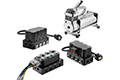
Product Description
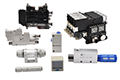
●Selection of the most suitable module for your application is possible by the modularized each unit and rich combination of units.
●Blow-Off Mechanism can be selectable from solenoid valve type and air timer (air chamber) type. The built-in switching
valve realizes fine tuning of quick blow-off air and fine adjustment of air rate.
●Easy maintenance by a lock-on manual button.
● 2 vacuum sensor selections: LED display Type and Mechanical Type which is simple and user-friendly.
● An LED display is used for LED digital pressure sensor to enhance visibility.
● Two types of vacuum switch : 2 switch output, 1 switch output with 1 analog output are available depending on the
desired application.
●4 Standard nozzle bores are 05(ø0.5mm), 07(ø0.7mm),10(ø10mm) and 12(ø1.2mm).

| Working medium | Air |
| Working pressure | 0.25~0.7MPa |
| Rated supply pressure | H and L type:0.5MPa/ E type: 0.35MPa |
| Working temperature | 5~50℃(No freezing) |
| Lubrication | Not required |
Product Specification
VK Series Vacuum generator
VK A① H② 07③ W④ - 1/4⑤ 1/4⑥ S⑦ E⑧ - B⑨ □⑩ -NW⑪
① A → Port orientation
| Code | Port orientation |
| A | Stand-alone type with double side port |
| B | Stand-alone type with single side port |
| M | Manifold Solenoid |
② H → Vacuum characteristics
| Code | Performance |
| H | High-vacuum type [Rated supply pressure 72.5 psi (0.5MPa)] |
| L | Large-flow type [Rated supply pressure 72.5 psi (0.5MPa)] |
| E | High-vacuum at low air supply pressure type [Rated supply pressure 50 psi (0.35MPa)] |
③ 07 → Nozzle bore.(Combinations: A, C, E, G, J, L, P, Q, R, S, T and W)
| Code | Nozzle bore(mm) | Vacuum level Suction flow | Air consumption | ||
H type | L type | E type | |||
| 05 | 0.5 | -26.8inHg, 0.25scfm (-91kPa,7L/min[ANR]) | -19.8inHg,0.42 scfm(-67kPa,12L/min[ANR]) | – | 0.41scfm (11.5L/min[ANR]) |
| 07 | 0.7 | -27.6inHg, 0.46scfm (-93.1kPa, 13L/min[ANR]) | -19.8inHg,0.91scfm (-67kPa, 26L/min[ANR]) | -27inHg, 0.37scfm (-91kPa, 10.5L/min[ANR]) | 0.81scfm(0.6scfm)(23L/min[ANR] (17L/min[ANR]) |
| 10 | 1.0 | -27.6inHg, 0.95scfm (-93kPa, 27L/min[ANR]) | -19.8inHg,1.4scfm (-67kPa, 40L/min[ANR]) | -27inHg,0.37scfm (-91kPa, 21L/min[ANR]) | 1.63scfm(1.2scfm)(46L/min[ANR] (34L/min[ANR]) |
| 12 | 1.2 | -27.6inHg, 1.33scfm (-93kPa, 38L/min[ANR]) | -19.8inHg,1.75scfm (-67kPa, 50L/min[ANR]) | -27inHg,0.95scfm (-91kPa, 27L/min[ANR]) | 1.63scfm(1.2scfm)(46L/min[ANR] (34L/min[ANR] |
| No code | Manifold-base alone | ||||
Nozzle bore. (Combinations: B, D, F, H, K and M)
| Code | Nozzle bore(mm) | Vacuum level Suction flow | Air consumption | ||
H type | L type | E type | |||
| 05 | 0.5 | -25.5inHg, 0.19scfm (-86.5kPa,5.4L/min[ANR]) | -19.6inHg,0.35scfm (-67kPa,12L/min[ANR]) | – | 0.41scfm (11.5L/min[ANR]) |
| 07 | 0.7 | -26.7inHg, 0.39scfm (-90.5kPa, 11L/min[ANR]) | -19.6inHg,0.67scfm (-66.5kPa,19L/min[ANR]) | -25.5inHg, 0.3scfm (-86.5kPa, 8.4L/min[ANR]) | 0.81scfm(0.6scfm)(23L/min[ANR] (17L/min[ANR]) |
| 10 | 1.0 | -26.7inHg, 0.67scfm (-90.5kPa, 19L/min[ANR]) | -19.6inHg,0.85scfm (-66.5kPa,24L/min[ANR]) | -25.5inHg,0.54scfm (-86.5kPa, 15.4L/min[ANR]) | 1.63scfm(1.2scfm)(46L/min[ANR] (34L/min[ANR]) |
| 12 | 1.2 | -26.7inHg, 0.85scfm (-90.5kPa, 24L/min[ANR]) | -19.6inHg,0.95scfm (-66.5kPa,27L/min[ANR]) | -25.5inHg,0.67scfm (-86.5kPa, 19L/min[ANR]) | 2.47scfm(1.67scfm)(70L/min[ANR] (47L/min[ANR] |
| No code | Manifold-base alone | ||||
※ⅰSuction flow of the vacuum port size with 5/32" O.D. and ø4mm may be different from the above values.
※ ⅱ Supply pressure is 72.5psi (0.5MPa) for H and L type and 50psi (0.35MPa) for E type.
※ ⅲ Air consumption values in ( ) represents that of E type.
※ ⅳ The values in the table are reference values only. Suction flow varies according to the vacuum system conditions; vacuum port dia. or tube length.
④ W → Combinations (18 types)
| Code | A | B | C | D | E | F | G | H | J | K | L | M | P | Q | R | S | T | W |
| Filter | ○ | ○ | ○ | ○ | ○ | ○ | ○ | ○ | ○ | ○ | ○ | ○ | ○ | ○ | ○ | ○ | ○ | ○ |
| Suction solenoid valve | ― | ― | ― | ― | ― | ― | ○ | ○ | ○ | ○ | ○ | ○ | ○ | ○ | ○ | ○ | ○ | ○ |
| Check valve (vacuum retention feature | ― | ○ | ― | ○ | ― | ○ | ― | ○ | ― | ○ | ― | ○ | ― | ― | ― | ― | ― | ― |
| Mechanical vacuum switch | ― | ― | ○ | ○ | ― | ― | ― | ― | ○ | ○ | ― | ― | ― | ○ | ― | ― | ○ | ― |
| Vacuum switch with LED display | ― | ― | ― | ― | ○ | ○ | ― | ○ | ○ | ― | ― | ○ | ― | ― | ○ | ― | ― | ○ |
| Air timer type blow-off valve | ― | ― | ― | ― | ― | ― | ― | ― | ― | ― | ― | ― | ○ | ○ | ○ | ― | ― | ― |
| Solenoid valve type blow-off pilot valve | ― | ― | ― | ― | ― | ― | ― | ― | ― | ― | ― | ― | ― | ― | ― | ○ | ○ | ○ |
| No code | Manifold-base alone | |||||||||||||||||
⑤ 1/4 → Vacuum port (tube dia.)
| Code | inch size | mm size | ||||
| 5/32 | 1/4 | 5/16 | 04 | 06 | 08 | |
| Tube dia.(mm) | Φ5/32 | Φ1/4 | Φ5/16 | Φ4 | Φ6 | Φ8 |
※5/32" (code: 5/32) and ø4mm (code: 04) is selectable for Nozzle Bore 0.5mm and 0.7mm only.
■ Manifold type (VKM)
| Port position | inch size | mm size | ||||||||||||
| Side (Straight) | Top (Straight) | Side (Straight) | Top (Straight) | |||||||||||
| Code | S5/32 | S1/4 | S5/16 | PP | T5/32 | T1/4 | T5/16 | S4 | S6 | S8 | PP | T4 | T6 | T8 |
| Tube dia. | Φ5/32 | Φ1/4 | Φ5/16 | Plug | Φ5/32 | Φ1/4 | Φ5/16 | Φ4 | Φ6 | Φ8 | Plug | Φ4 | Φ6 | Φ8 |
00:Applicable to a manifold installation top-mounting unit alone, with the port to be installed on the side and to model code for manifold-base alone with different vacuum port size.
※ ⅰ5/32" (code: 5/32) and ø4mm (code: 04) is selectable for Nozzle Bore 0.5mm and 0.7mm only.
※ ⅱRefer to the Manifold Type reference picture to select the port position.
⑥ 1/4 → Air supply port (tube dia.)
■ Stand-alone type
| Code | inch size | mm size | ||||
| 5/32 | 1/4 | 5/16 | 04 | 06 | 08 | |
| Tube dia.(mm) | Φ5/32 | Φ1/4 | Φ5/16 | Φ4 | Φ6 | Φ8 |
※5/32" (code: 5/32) and ø4mm (code: 04) is selectable for Nozzle Bore 0.5mm and 0.7mm only.
■ Manifold type (VKM)
| Port position | inch size | mm size | |||||||||||||
| Straight | Elbow | Straight | Elbow | ||||||||||||
| Code | R side only | 11/4 | 15/16 | 13/8 | 11/2 | 45/16 | 43/8 | 41/2 | 16 | 18 | 10 | 12 | 48 | 40 | 42 |
| Both sides | 21/4 | 25/16 | 23/8 | 21/2 | 55/16 | 53/8 | 51/2 | 26 | 28 | 20 | 22 | 58 | 50 | 52 | |
| L side only | 31/4 | 35/16 | 33/8 | 31/2 | 65/16 | 63/8 | 61/2 | 36 | 38 | 30 | 32 | 68 | 60 | 62 | |
| Tube dia. | Φ1/4 | Φ5/16 | Φ3/8 | Φ1/2 | Φ5/16 | Φ3/8 | Φ1/2 | Φ6 | Φ8 | Φ10 | Φ12 | Φ8 | Φ10 | Φ12 | |
00:Applicable to a manifold installation top-mounting unit alone.
⑦ S → Exhaust port (tube dia.)
■ Stand-alone type
| Code | S | 08 | L8 |
| Tube dia. | Silencer vent | Φ8mm Straight type 8mm is same as 5/16" (tube exhaust) | Φ8mm Elbow type 8mm is same as 5/16" (tube exhaust) |
■ Manifold type (VKM)
| inch size | ||||||||||||
| Port type | Silencer vent | Tube exhaust | ||||||||||
| Straight | Elbow | Female taper thread | ||||||||||
| Code | R side only | S1 | 15/16 | 13/8 | 11/2 | 15/8 | 45/16 | 43/8 | 41/2 | 72N | 73N | 74N |
| Both sides | S2 | 25/16 | 23/8 | 21/2 | 25/8 | 55/16 | 53/8 | 51/2 | 82N | 83N | 84N | |
| L side only | S3 | 35/16 | 33/8 | 31/2 | 35/8 | 65/16 | 63/8 | 61/2 | 92N | 93N | 94N | |
| Tube dia. | ― | Φ5/16 | Φ3/8 | Φ1/2 | Φ5/8 | Φ5/16 | Φ3/8 | Φ1/2 | 1/4NPT | 3/8NPT | 1/2NPT | |
| mm size | ||||||||||||
| Port type | Silencer vent | Tube exhaust | ||||||||||
| Straight | Elbow | Female taper thread | ||||||||||
| Code | R side only | S1 | 18 | 10 | 12 | 13 | 48 | 40 | 42 | 72 | 73 | 74 |
| Both sides | S2 | 28 | 20 | 22 | 23 | 58 | 50 | 52 | 82 | 83 | 84 | |
| L side only | S3 | 38 | 30 | 32 | 33 | 68 | 60 | 62 | 92 | 93 | 94 | |
| Tube dia. | ― | Φ8 | Φ10 | Φ12 | Φ16 | Φ8 | Φ10 | Φ12 | Rc1/4 | Rc3/8 | Rc1/2 | |
00:Applicable to a manifold installation top-mounting unit alone.
⑧ E → Solenoid valve type
| Voltage | DC24V | AC100V |
| Normally closed (N.C.) | E | F |
| Normally open (N.O.) | G | H |
⑨ B → Color
| Code | W | B |
| Color | Light-gray | Black |
⑩ □ → Number of stations (Manifold type only)
| Code | N02 | 03 | 04 | 05 | 06 | 07 | 08 | 09 | 10 |
| # of stations | 2 | 3 | 4 | 5 | 6 | 7 | 8 | 9 | 10 |
※ Special-order for those with 11 or more stations.
⑪ □ → Vaccum switch (※ Selectable only when ④Combinations is one of E, F, L, M, R and W)
| Code | -NW | -NA | -PW | -PA |
| Switch output | NPN open collector output with 2 switch outputs | NPN open collector switch output and analog output | PNP open collector output with 2 switch outputs | PNP open collector switch output with analog output |
Main Dimensions
■ Piping Example
■ Construction (Stand-alone type with double side port : VKA)

■ Construction (VKB: Stand-alone type with single side port)


 English