sales@vpc-pneumatic.com 0086-13989308920 


Product Description
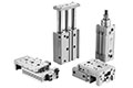
1. Metal seal structure reduces the coefficient of friction of the cylinder, thus reducing the piston rod sliding resistance.
2. Extremely low sliding resistance, low pressure drive of 0.005 MPa is possible.
3. High stability, no increase in sliding resistance even after long periods of inactivity.
4. Lateral load resistance is increased by built-in ball bushing.
5. Smooth, uniform speed actuation ranges as low as 0.3 mm/s.
6. Extended lifespan of up to 10,000 km or 100 million full cycles.
7. Bore size options: 16, 20, 25 mm
8. A wide range of mounting options are available, including foot type, rod-side flange type, head side flange type, single and double clevis type.
※ VPC support customization of low-friction cylinders with other specifications or special needs.

Product Specifications
| Bore size (mm) | 16 | 20 | 25 | |
| Seal construction | Metal seal | |||
| Actig type | Double acting, Single rod | |||
| Working medium | Air | |||
| Proof pressure | 1.05 MPa | |||
| Max. working pressure | 0.7 MPa | |||
| Min. working pressure | 0.005 MPa | |||
| Working temperature | -10 to 80 ℃ | |||
| Piston speed | 0.5 to 1000 mm/s | |||
| Cushion type | Rubber bumper | |||
| Tolerance of stroke | 1.0 mm 0 | |||
| Lubrication | Not required | |||
| Total leakage | Supply pressure 0.1 MPa | 250 cm³/min | 300 cm³/min | |
| Supply pressure 0.3 MPa | 1000 cm³/min | 1200 cm³/min | ||
| Supply pressure 0.5 MPa | 2500 cm³/min | 3000 cm³/min | ||
Main Dimensions

▲ Caution
1. When mounting, thoroughly flush out the connector piping and be sure that dirt and chips, etc., do not
get inside the cylinder.
2. Install an air filter with a filtration degree of 5 µm or less on the air supply. Furthermore, when controlling for low speed or controlled output, use clean air (atmospheric pressure dew point temperature of –10°C). Installation of a mist separator (filtration degree 0.3 µm or less) is also recommended.
3. Use a metal seal type when using solenoid valves for cylinder actuation. If a rubber seal type is used, there may be an increase in operating resistance due to grease sprayed from the main valve.
4. Operate so that the load applied to the piston rod is normally in the axial direction. In the event that a lateral load is unavoidable, do not exceed the range of the allowable lateral load at the rod end.
5. Take care not to scratch or gouge the sliding portion of the rod. This may cause malfunction or shorten the unit's life.
6. When attaching a work piece to the end of the rod, move the rod to the fully retracted position and use the wrench flats at the end of the rod. Fasten the work piece without applying a large amount of torque to the rod.
7. Be certain to connect a load so that the rod axis is aligned with the load and its direction of movement.
Especially when a cylinder rod is connected directly to a guide function (such as bearings, etc.) on the equipment side, the following is likely to occur. Either an offset load will occur and the sliding resistance will not be stable or galling will occur on the metal seal parts. Therefore, be sure to use a floating joint or a spherical joint.
8. When a piston rod is driven with a circuit from an external force such as force, control, tension control, etc., a stick-slip phenomenon will likely occur and sliding resistance will not be stable if the amount of displacement is 0.05 mm or less.
Catalogue PDF


 English