sales@vpc-pneumatic.com 0086-13989308920 


| Pressure specification: | |
|---|---|
| Guaranteed pressure: | |
| Port size: | |
| Thread type: | |
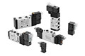
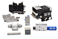
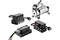
Product Description
1. Low power consumption
DC4 W (Standard type), DC1.8 W (Energy-saving type)
No lubrication required. Possible to use in vacuum or under low pressures
2. External pilot
Vacuum: Up to –101.2 kPa, Low pressure: 0 to 0.2 MPa
3. Changeable actuation: N.C., N.O., or external pilot
4. Can be used as a selector or divider valve (External pilot)


* Use external pilot type in the following cases:
1)For vacuum or for low pressure 0.2 MPa or less.
2)When having P port downsized in diameter.
Product Specifications
| Type of actuation | In common between N.C. and N.O. | |
| Working medium | Air | |
| Acting type | Internal pilot type | External pilot type |
| Working pressure | 0.2 to 0.9 MPa | -101.2 kPa to 0.9 MPa |
| External pilot operating pressure range | - | Same as the operating pressure (Min. 0.2 MPa) |
| Response time*1) | 30 ms or less (at the pressure of 0.5 MPa) | |
| Max. operating frequency | 5 c/s (Min. operating frequency: 1 c/30 days based on JIS B 8374-1981) | |
| Working temperature | -10 to 50°C (No freezing) | |
| Lubrication | Not required (Use turbine oil Class 1 ISO VG32, if lubricated.) | |
| Manual override | Push type (Non-locking) | |
| Mounting orientation | Unrestricted | |
| Impact/Vibration resistance*2) | 150/50 m/s2 | |
*1) Based on dynamic performance test JIS B 8419: 2010. (Coil temperature 20°C, at rated voltage, without surge voltage suppressor)
*2) Impact resistance: No malfunction occurred when it is tested with a drop tester in the axial direction and at the right angles to the main valve and armature in both energized and de-energized states every once for each condition. (Values at the initial period)
Vibration resistance: No malfunction occurred in a one-sweep test between 45 and 1000 Hz. Test was performed at both energized and de-energized states in the axial direction and at the right angles to the main valve and armature. (Values at the initial period)
| Port size | Flow Characteristics | |||||||||||
| 1→2(P→A) | 2→3(A→R) | 2→1(A→P) | 3→2(R→A) | |||||||||
C [dm³/(s·bar)] | b | Cv | C [dm³/(s·bar)] | b | Cv | C [dm³/(s·bar)] | b | Cv | C [dm³/(s·bar)] | b | Cv | |
| 1/2 | 26 | 0.38 | 7.0 | 27 | 0.37 | 7.4 | 27 | 0.36 | 7.3 | 25 | 0.37 | 6.8 |
| 3/4 | 38 | 0.30 | 9.8 | 38 | 0.32 | 9.8 | 40 | 0.22 | 9.8 | 40 | 0.20 | 9.6 |
| Port size | Effective area (mm²) | |
| 1→2(P→A) | 2→3(A→P) | |
| 1 | 210 | 235 |
| Electrical entry | Grommet (G), DIN terminal (D) | ||
| Enclosure | Dusttight | ||
| Coil rated voltage | AC(50/60 Hz) | 100V, 200V, 110V, 220V, 240V | |
| DC | 24V,12V | ||
| Allowable voltage fluctuation | -15 to+10% of rated voltage | ||
| Apparent power VA (Hz) | AC | Inrush | 12.7(50), 10.7(60) |
| Holding | 7.6(50), 5.4(60) | ||
| Power consumption | DC | Without indicator light: 4 W With indicator light: 4.2 W | |
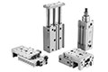
Product Dimensions


When changing the passage state, confirm that pressure has been removed from the valve. Unscrew the M4 x 0.7 hexagon socket head cap screw in the changeover plate and match the◀mark on the adapter plate with the character on the changeover plate. Piping is as follows.

Mounting Screw Tightening Torques
M4: 1.4 N·m
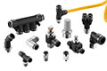
Piping
Fluide passage/Port | P | A | R |
N.C. | Inlet side | Outlet side | Exhaust side (Plug, in case of 2 port valve) |
N.O. | Exhaust side (Plug, in case of 2 port valve) | Outlet side | Inlet side |
External | Universal porting (Piping of inlet pressure side is possible anywhere) | ||
*1) In the case of internal pilot, confirm that a plug is inserted to X port. If not, insert a R 1/8 plug.
*2) In the case of external pilot, supply air pressure from X port.
Confirm the safety sufficiently and conduct carefully when changing the passage state or restarting after changes.


 English